Translate

Showing posts with label Programing. Show all posts

Sunday, 15 June 2014

Analog / Digital Converter with I2C

In this program we will perform an analog / digital conversion using the I2C protocol. 

We will use the Pic 18F4550 and CAD PCF8591, displaying the result on a LCD display.

For its operation will be necessary to use the library of display LCD_Flexible.C


In this exercise program the PCF8591  converter Digital-Analog-Digital 8-bit Analog to operate in mode Analog to Digital Converter.

The data read range from 0 to 0xFF × 00 because it is an 8-bit converter. Knowing that the reference voltage is 5V and there are 256 possible readings 

SPI Protocol:


ISIS Program: Use ISIS program to simulate the code.


PROGRAM CODE:
///////////////////////////////////////////////////////////////////////////////////////////
//   AUTOR: OSCAR GONZALEZ BURON                                            FEBRERO/2014
///////////////////////////////////////////////////////////////////////////////////////////
//   PROGRAMA: CAD I2C                                                VERSIÓN:    1.0
//   DISPOSITIVO: PIC 18F4550                                         COMPILADOR:    CCS vs4.023
//   Entorno IDE: MPLAB                                               SIMULADOR:    Proteus 8.0 sp1
//   TARJETA DE APLICACIÓN: UNIVERSAL Trainer                         DEBUGGER:    ICD3 
///////////////////////////////////////////////////////////////////////////////////////////
///////////////////////////////////////////////////////////////////////////////////////////
///////////////////////////////////////////////////////////////////////////////////////////
//     CONVERSOR ANALOGICO/DIGITAL PCF8591 CON PROTOCOLO SPI            //////////////////
///////////////////////////////////////////////////////////////////////////////////////////
///////////////////////////////////////////////////////////////////////////////////////////
// CABECERA ///////////////////////////////////////////////////////////////////////////////
///////////////////////////////////////////////////////////////////////////////////////////
#include <18f4550.h>
#fuses intHS,MCLR
#use delay(internal=8MHz)
#use i2c(Master, sda=PIN_B0, scl=PIN_B1)
#include <LCD_flexible.c>
///////////////////////////////////////////////////////////////////////////////////////////
// VARIABLES GLOBALES /////////////////////////////////////////////////////////////////////
///////////////////////////////////////////////////////////////////////////////////////////

float valor=0;

///////////////////////////////////////////////////////////////////////////////////////////
// FUNCIONES //////////////////////////////////////////////////////////////////////////////
///////////////////////////////////////////////////////////////////////////////////////////

///////////////////////////////////////////////////////////////////////////////////////////
// PRINCIPAL //////////////////////////////////////////////////////////////////////////////
///////////////////////////////////////////////////////////////////////////////////////////
void main()
{
   i2c_start();               //iniciar comunicación i2c.
   i2c_write(0b10010000);         //dirección (7bits). El último bit determina si se lee o se escribe
   i2c_write(0b00110000);         //byte de control (El 11 activa las entradas analógicas en modo diferencial)
   i2c_start();               //iniciar comunicación i2c.
   i2c_write(0b10010001);         //dirección (7bits). El último bit determina si se lee o se escribe
   lcd_init();
   for(;;)
   {
      valor=i2c_read();
      valor=valor/256;
      LCD_GOTOXY(1,1);
      printf(lcd_putc,"Tension = %1.2f Voltios",valor);
   }
      

   i2c_stop();                  //terminar comunicación i2c.


Thursday, 12 June 2014

Design Microcontroller Board - Proteus

All our designs are made with PROTEUS Software(Version 7-8) because is a very utility program to simulate and design electronics circuits.

Other important Software to design electronics boards are the EAGLE program, better if you need edit Layout board.

In this picture you can see ISIS program, in which you can design, simulate and debug electrics and electronics sistems and circuits with a large number of tools edit.

Especially in this picture can see at Atmel328p microcontroller System, with all necessary requeriments to run.

The next pricture corresponds to ARES program, in wich you conects all the componets you use in a schematic window(ISIS). 

The principal function in this program is do all the layerout of the board, conectind all components in his respective layers(Top,Bottom) with the NET (T20) and VIAS(V60).
After finishing the design of the plate and all their connections, Files for its creation are generated. For this we need to export the layers of Drill, top, bottom, and edge board mech1 in Gerber / Excellon files. --->ARES/Output/Generate Gerber/Excellon Files


After that, you can made the printed circuit board by CNC machine, or do the Drill Layout by Bungard machine  and the Top/Botton Layout by acid revealed.


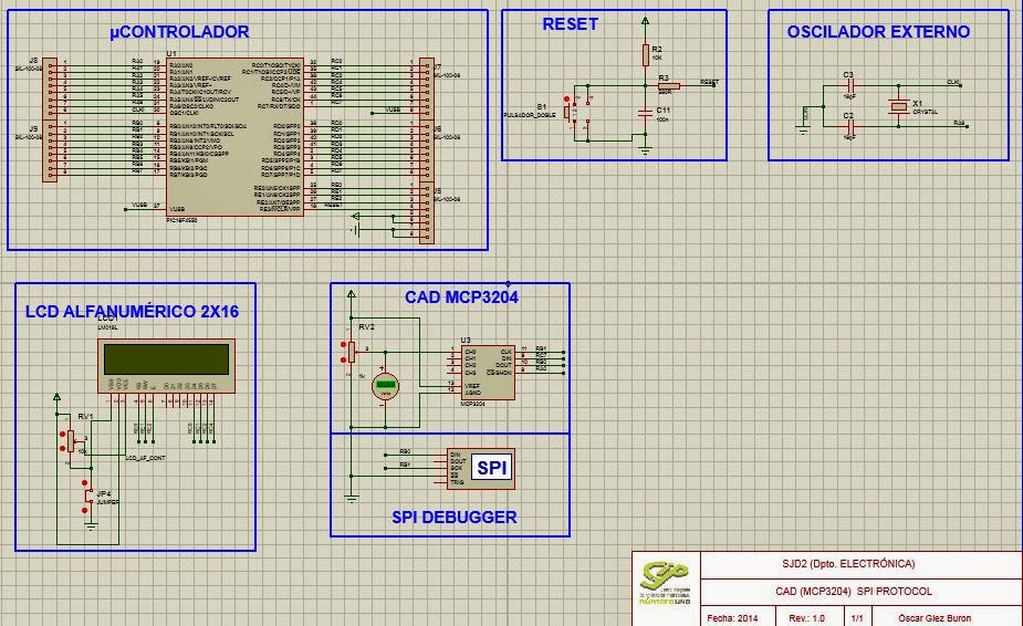
Analog / Digital Converter with SPI

In this program we will perform an analog / digital conversion using the SPI bus. 

We will use the Pic 18F4550 and CAD MCP_3204, displaying the result on a LCD display.

For its operation will be necessary to use the library for use MCP_3204.C CAD SPI, and library of display LCD_Flexible.C

SPI Protocol:


ISIS Program: Use ISIS program to simulate the code.


PROGRAM CODE

///////////////////////////////////////////////////////////////////////////////////////////
//   AUTOR: OSCAR GONZALEZ BURON                                             ENERO/2014
///////////////////////////////////////////////////////////////////////////////////////////
//   PROGRAMA:    CAD_SPI                                    VERSIÓN:    1.0
//   DISPOSITIVO: PIC 18F4550                                COMPILADOR:    CCS vs4.023
//   Entorno IDE: MPLAB                                      SIMULADOR:    Proteus 8.0 sp1
//   TARJETA DE APLICACIÓN: UNIVERSAL TRAINER                DEBUGGER:    ICD3
///////////////////////////////////////////////////////////////////////////////////////////
///////////////////////////////////////////////////////////////////////////////////////////
///////////////////////////////////////////////////////////////////////////////////////////
//   CONVERSOR ANALOGICO/DIGITAL MCP3204 CON PROTOCOLO SPI    ////////////////////////////
///////////////////////////////////////////////////////////////////////////////////////////

////////////////// Driver for MCP3204 A/D Converter ////////////////////////
////                                                                     ////
////  adc_init()                                                          ////
////      Call after power up                                             ////
////                                                                       ////
////  value = read_analog_mcp( channel, mode )                             ////
////      Read an analog channel                                            ////
////      0 through 3 and select                                          ////
////      differential (0) or                                             ////
////      single (1) mode                                                  ////
////                                                                       ////
////  value = read_analog( channel )                                      ////
////      Read an analog channel                                           ////
////      0 through 7 in   single mode                                        ////
////                                                                       ////
////  convert_to_volts( value,  string )                                 ////
////      Fills in string with                                             ////
////      the true voltage in                                             ////
////      the form 0.000                                                   ////
////                                                                      ////
////////////////////////////////////////////////////////////////////////////
////        (C) Copyright 1996,2003 Custom Computer Services            ////
//// This source code may only be used by licensed users of the CCS C   ////
//// compiler.  This source code may only be distributed to other       ////
//// licensed users of the CCS C compiler.  No other use, reproduction  ////
//// or distribution is permitted without written permission.           ////
//// Derivative programs created using this software in object code     ////
//// form are not restricted in any way.                                ////
////////////////////////////////////////////////////////////////////////////

///////////////////////////////////////////////////////////////////////////////////////////
// CABECERA ///////////////////////////////////////////////////////////////////////////////
///////////////////////////////////////////////////////////////////////////////////////////
#include <18f4550.h>
#fuses XT,MCLR
#use delay(clock=20000000)
#include <LCD_flexible.c>
#include <D:\Proyectos Electronica\Project_IDE\2º\CAD_3204>
///////////////////////////////////////////////////////////////////////////////////////////
// VARIABLES GLOBALES /////////////////////////////////////////////////////////////////////
///////////////////////////////////////////////////////////////////////////////////////////

long int valor;
float voltaje;
///////////////////////////////////////////////////////////////////////////////////////////
// FUNCIONES //////////////////////////////////////////////////////////////////////////////
///////////////////////////////////////////////////////////////////////////////////////////

///////////////////////////////////////////////////////////////////////////////////////////
// PRINCIPAL //////////////////////////////////////////////////////////////////////////////
///////////////////////////////////////////////////////////////////////////////////////////
void main()
{
   lcd_init();
   adc_init();
   lcd_putc("CAD MCP3204 I2C");
   for(;;)
   {
      valor = read_analog(0);
      voltaje = (valor*5.0)/4096;   //Regla de 3; el dato es igual al valor leido multiplicado por Vref(5V) y                                                         //dividido entre el nº de bits del CAD (12bits=4096)
      LCD_GOTOXY(1,2);
      printf(lcd_putc,"Voltaje = %f V", voltaje);
   }
}


Wednesday, 28 May 2014

LabView - Data Acquisition, Charge and Discharge of a Capacitor.

In the following program which will do is make the acquisition of data loading and discharge of a capacitor with Data Adquisition(MyDAQ) of National Instruments sampling and plot a graph to visualize it and look how long it takes.

On the Front Panel we can see the explanation of the exercise, the load carried and the graph in which the acquisition is shown.
Furthermore we can control the plot of the chart to see the exact location of data and the time it is performed, while entering data in the load and make sure they match.
FrontPanel

First create a channel to perform data acquisition, to configure it in the properties of your analog input DAQ using the differential mode and select the properties of the acquisition. (channel, mode, range, type, frequency....), after this timing the sampling buffer for acquisition and allow time for reading and plotting the data on the graph
Block Diagram
Block Diagram- Calculators

This are the mathematical calculation of the charge and dischargue of the capacitor. Using the differents information of the components used. (resistor and capacitor). 
Use the mathematical formula and created the algorithm with the mathematical tools Labview.


IMPORTANT: For the data acquisition is accurate according to the values ​​of the resistor and capacitor used, is necessary precompute the value of the internal resistance of the DAQ and use a resistance at least 10 times to so despise their value and not altered its acquiring.

To perform a data acquisition wiring components and Daq must be properly made.

Using the analog channel zero for the acquisition; as input for the creation of differential channel signal acquisition and output as write mode RSE.

To make a good acquisition first configure the myDAQ, setting the analog input (ai0) myDAQ for the acquisition of data in differential mode (DIF) and setting the analog output (AO0) for signal generation mode RSE.


Wednesday, 19 June 2013

TIA Portal de Siemens. Uso y programación de PLC'S

Mediante el uso del programa TIA Portal de Siemens conseguimos realizar programas que nos permiten controlar y programar PLC'S con una simulación previa a su cargado. Esto se consigue gracias a un entorno de trabajo que permite la conexión del PLC con el ordenador de forma sencilla asignando una IP mediante una conexión Ethernet.

La Programación se realiza mediante los utensilios del programa TA Portal, que pone a nuestra disposición todas las herramientas necesarias para la programación mediante el lenguaje KOP que permite asignar marcas, entradas y salidas de manera sencilla realizando la simulación y posterior programación del PLC de forma sencilla y evitando errores.

Aquí  os dejo un vídeo en el que se muestra el proceso de programación de un PLC S-1200 mediante el lenguaje KOP y su conexión a una maqueta neumática:


¿Que aspectos del Blog se podrían mejorar?